CS40 Midterm Project: Raytracing
You may work with one partner on this assignment. This lab will count as your midterm project and use a variety of techniques that you have learned so far. You will design and implement a ray tracer. Your ray tracer should model spheres, triangles, and rectangles, using the Phong lighting model for ambient, diffuse, and specular lighting. You should also model shadows.
$ cd
[~]$ ssh-add
Enter passphrase for /home/ghopper1/.ssh/id_rsa:
Identity added: /home/ghopper1/.ssh/id_rsa (/home/ghopper1/.ssh/id_rsa)
[~]$ cd ~/cs40/
[cs40]$ git clone git@github.swarthmore.edu:CS40-F18/raytracer-YOURUSERNAME-YOURPARTNERNAME.git raytracer
Making and building code
Make a build directory in yourraytracer directory and run cmake ../ and make.
[raytracer]$ cd ~/cs40/labs/raytracer
[raytracer]$ mkdir build
[raytracer]$ cd build
[build]$ cmake ..
[build]$ make -j8
[build]$ ./raytracer scenes/input.txt
You program does not display a window. Instead it creates a png image file (
test.png as specified in input.txt). You can view image files on the CS system using the program eog. The image should be a blank black image at this point. Your raytracer code will construct the correct image.
input.txt for a sample test file describing a scene to model and the viewpoint from which to raytrace the final image.
The image plane
The first few lines of this file describe the name of the output image and the height and the width of the image (in pixels)
#comment
output test.png
outsize 512 512
This image also represents a planar rectangle in the world. This rectangle is specified by the lower left corner of the rectangle and two vectors: a horizontal vector pointing from the lower left to the lower right, and a vertical vector pointing from the lower left to the upper right.
origin -5 -5 8
horiz 10 0 0
vert 0 10 0

The center of every pixel at row, column in the output image file has a corresponding position in world coordinates using origin, horiz and vert.
The eye
The $x,y,z$ location of the eye in world coordinates is specified with theeye keyword.
eye 0 0 15You will be tracing rays from the eye location through the center of each pixel to the scene, usually located on the opposite side of the image plane from the eye.
Shapes
You are asked to support, at the minimum, three shapes: spheres, triangle, and rectangles. A sphere should be represented by a center and radius#center x,y,z radius sphere 0 0 0 2
Triangles and rectangles will be specified by three points. In the case of rectangles, assume the first three points are the lower left, lower right, and upper right, respectively. You can compute the upper left with this information.
#xyz of p1,p2,p3
triangle -5 5 5  5 5 5  5 5 -5

#xyz of ll, lr, ur
rectangle -5 -5 5  5 -5 5  5 -5 -5
Shape.h describes a virtual base class, much like the Drawable class from lab 02. It is important that each shape you add to your scene is able to compute intersections with rays and the shape. Also, each shape should compute normals for points on the shape. You should implement spheres, triangles, and rectangles as classes derived from the Shape class. I have started this for you in Sphere.h, but you need to add some stuff and implement the appropriate methods in Sphere.cpp. Don't forget to update your CMakeLists.txt file. You will need to add Triangle and Rectangle classes from scratch.
Lights
Lights in the input file are of two forms: point lights that contribute to diffuse and specular lighting and a single global ambient light that contributes overall background lighting. The global ambient lighting should in general have a low intensity, but you can bump it up while debugging. Point light sources have a position in world space and an intensity.
#global ambient intensity
amblight 0.1

#xyz pos intensity
light 0 3 10 0.3
light -5 0 0 0.3
light 5 8 0 0.3
QImage and QColor are from Lab 01. Recall that in the QImage class, pixel 0,0 is in the upper left.
view, material, light, ray and hit are very lightweight classes or structs that just are containers for grouping related elements together. In many cases, there is no associated cpp files since the member variables can be accessed directly. Feel free to modify these classes/structs if you like, but you shouldn't need to add a ton of stuff to these files to get a basic ray tracer working.
common.h currently just contains the vec3 typedef. Feel free to add other "common" functions here if needed, and add a common.cpp if the code complexity grows.
makescene.cpp is a small wrapper around the bulk of the raytracer. This is the main executable you run. It checks that you provided an input file, creates an instance of the RayTracer class, parses the file, traces the scene, and saves the result. You do not need to modify this code. Instead, modify raytracer.cpp.
If you look at raytracer.cpp initially, you'll see that RayTracer::save() creates a QImage object and saves it to a file. You will probably want to move the creation of this image into RayTracer::trace(), make the QImage object a member variable, and only have save write the output image created in trace(). This was my final implememtation of save:
void RayTracer::save() {
  if(m_img){
    m_img->save(m_view.fname, "PNG");
    qDebug() << "Saved result to " << m_view.fname;
  }
}
That leaves the parser, which reads a text file like input.txt and converts it into an internal format that your raytracer can use. Writing parsers in C++ can be very tedious. I got you started by writing some helper function in parser.h. Reading this file may be helpful as you parse some commands I have left out. Reading parser.cpp is probably less helpful. It has the tedious and annoying details of C++/Qt string manipulation. raytracer.cpp contains the start of a full parser that opens the input file and parsers each command line by line. Check out parseLine which is similar to a giant switch statement (except you can't switch on string types). When you run the parser initially, you will find some commands are completely missing and some are only partially implemented. Examine the other parts of parseLine and use it to fill in any missing details. It is recommended that you store all the information about the input file in the m_scene object.
I use two QHash dictionaries in the parser to refer to certain color and material variables by a string name, like "red". Take a look at a few examples in the parser and feel free to ask questions.
To make material handling a bit easier, there is a notion of the "current" material. Changing the properties of a material through the use of mat amb color changes the "current" material which can be saved as a special name and retrieved later. When you create a new sphere, triangle, or rectangle, you do not need to specify nine material coefficients. The semantics is that these objects should just use the "current" material at the time the object is created. It's very OpenGL-esque, for better or worse.
As for implementing the actual raytracer, it is helpful to have a function that can convert i,j png pixel coordinates to world coordinates using the origin, horiz and vert point/vector information. For each pixel, create a ray from the eye to the pixel position in world coordinates then have a function that traces one ray and returns a single QColor which can be assigned to the final output png file.
Don't try to handle all the components at once. Focus on maybe getting the ambient lighting working for one sphere or one rectangle in the center of the image. Once you have the basic outline correct, adding diffuse and specular lighting should be easier.
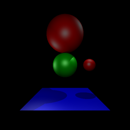
- successfully parse and render the original
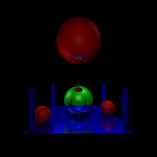
input.txtfile as shown below - design your own scene file and render it.
- support spheres, triangles, and rectangles
- support multiple light sources
- support global ambient lighting
- support diffuse and specular lighting
- support shadows
- reflective surfaces
- refractive semi-transparent solids
- spot lights
- texture mapping of rectangles and/or spheres
- anti-aliasing via super-sampling
- support for other shapes, e.g., cylinders, or cones
You do not need a draw method in your shape classes. The drawing is done by the rays traveling through the image plane.
You do not need a perspective or ortho projection matrix. As all rays originate from the origin and go through the image plane, you will get a perspective effect from simply tracing rays.
RayTracer::Run():

  init Image
  for each col,row in Image:
    ray = MakeRay(col, row)
    clr = TraceRay(ray)
    Image(col, row) = clr
  Image.save()
makeRay
RayTracer::MakeRay(col, row):
  /* Use origin, horiz, vert, nrows, ncols to
   * map col, row to point in world coordinates */
  Point p = ConvertToWorld(col,row)
  Ray ray
  ray.origin = eye
  ray.direction = p-eye
  return ray
traceRay
RayTracer::TraceRay(ray):

  Hit closest = FindClosestShape(ray)
  Color clr = background
  if closest.ID != -1:
    /* We hit a shape with the ray, compute
     * color using lighting model */
    clr = DoLighting(ray, closest.shape)
  return clr
doLighting
RayTracer::DoLighting(ray, shape):
  /* include global ambient */
  clr = ambient*shape.clr;
  for each light L:
    if shape not in shadow of L:
       clr += phong(ray, L, shape)
  return clr
findClosest
RayTrace::FindClosest(ray):

 closest.ID = -1 /* haven't found anything yet */
 for each object O:
   time = O.hitTime(ray)
   if time > 0:
      if closest.ID == -1 or time < closest.time:
         /* O is closer, update closest */