Lab 02: Basic Circuits
Introduction
In this lab, you will build six circuits using the logisim program that we used in class. Type logisim on the command-line to begin the program. You can test each of your programs using input and output pins, as demonstrated in class. Be sure to save often as logisim will not autosave your circuits as you work. You can find documentation, as well as download logisim for your Mac/Windows/Linux machine, from the logisim website.
When you create a circuit, be sure you give your inputs and outputs appropriate labels. All of the circuits (except the first) build on one another and these labels will come in handy when trying to wire them up.
As with all labs, be sure you adequately test your solution with a range of input values in order to validate that your solution matches what you expect.
You will work alone on this assignment.
The handin33 program will only submit files found in the cs33/lab/02 directory. You will create only two files, adders.circ, which will hold all of the circuits you create in the first half of the lab, and alu.circ, which will hold all of the circuits you create in the second half of the lab.
Part 1: Building and using a full adder
Your answers to Part 1 will be stored in adders.circ.
Sign Extension
Sign extension (section 2.5.2) is an common operation performed inside a CPU. Create a circuit (Project→Add Circuit) that takes a 4-bit 2's complement number and performs sign extension so that the output is an equivalent 8-bit 2's complement number. Be sure to label each of your input and output values. Your input should be labeled so that the least significant input bit is a0 and the most significant input bit is a3. Following the same pattern, label your output bits b0 through b7.
1-bit Full Adder
Using either the circuit on page 62 or your own design, create a 1-bit full adder as a new circuit (Project→Add Circuit). Name this circuit fulladder. Your full adder should take 3 inputs (A, B, CarryIn) and yield two outputs (Sum, CarryOut).
4-bit Full Adder
Add a new circuit fulladder4 that can add two 4-bit unsigned numbers. (Your 4-bit number should be represented as 4 1-bit inputs, not 1 4-bit input.) Your solution will use the fulladder from the previous question. Your inputs should be a3...a0 and b3...b0. Your output will be c3...c0.
Do not worry about overflow yet, but do hook up a probe to the final CarryOut bit so you can access it later. NOTE: The 4-bit adder you are building adds two 4-bit numbers, whether they are unsigned or 2's complement. The only difference has to do with overflow -- which you aren't dealing with in this question -- the addition is the same either way.
4-bit Incrementer
Add a new circuit incrementer4 that takes a 4-bit number as input and outputs that number incremented by 1. Use your fulladder4 circuit in the solution. You do not need to worry about overflow. Use sensible names for the input and output.
4-bit Negater
Add a new circuit negater4 that negates a 4-bit 2's complement number. For example, an input of 0001 (+1) would yield an output of 1111 (-1). An input of 1110 (-2) would yield an output of 0010 (+2). (An input of 1000 will yield 1000. Why?) Your solution should use your incrementer4. Use sensible names for the input and output.
Part 2: Arithmetic Logic Unit
In this part of the lab, you will implement part of an arithmetic logic unit. Your answer will be stored in alu.circ. This is part of the computer that performs mathematical operations. Your ALU should use components from Logisim whenever possible. For example, do not build a 8-bit adder -- simply use the 8-bit adder that is already part of Logisim.
To use an 8-bit adder, open the Arithmetic folder and select Adder. The default Adder has "Data Bits" set to 8. That is an 8-bit adder. The inputs to an 8-bit adder are also 8-bits, so you need to hook up an 8-bit input pin. The output is 8-bits, so you need to hook up an 8-bit output pin. The carry-in and carry-out bits are only 1-bit each.
Your ALU will perform 8 functions on two 8-bit inputs, producing an 8-bit output, as well as three 1-bit outputs. You will select which of the 8 functions to perform using a multiplexor with 8 inputs and 3 select lines. (In Logisim, be sure to change "Include Enable?" from "Yes" to "No".) The function you perform will depend on the value of the 3 select lines. Assuming the inputs are called X and Y, you will perform:
- 000: X or Y
- 001: X and Y
- 010: X + Y
- 011: X - Y. Note that Logisim contains a Subtractor circuit which you should use.
- 100: X << Y. Shift left. e.g. 10111000 becomes
01110000. Note that Logisim has a Shifter gate that can be
customized to perform this and the next three
operations. Shifts X to the left Y times. Note: for the
three shift operations, the input Y to the Shifter can only
be 3 bits. Use a splitter to extract the last three bits of
Y, then use another splitter (in reverse) to build up a 3
bit wire from the 3 least significant digits. If
Y=01010100, you would shift
01010100 -- 4 places to the left. - 101: X >> Y (Shift right) without sign extension (also known as logical shift), e.g. 10111001 becomes 01011100, not 11011100. Shifts X to the right Y times; the input Y is still only 3 bits.
- 110: X >> Y (Shift right) with sign extension (also known as arithmetic shift), e.g. 10111001 becomes 11011100 and 01000001 becomes 00100000; the input Y is still only 3 bits.
- 111: X < Y? The output should be 00000001 if X < Y 00000000 otherwise. X and Y should be treated as 2's complement values. Logisim has a Comparator gate that can be customized to perform almost exactly what you need, but it only ouputs a 1-bit 0 or 1, so you'll need to figure out how to make that 8 bits.
Your ALU will also have 3 1-bit output "flags":
- Equals: This output will be 1 whenever X == Y; 0 otherwise.
- Unsigned overflow: This output should be 1 whenever:
- X + Y would have resulted in overflow if X and Y were unsigned. This happens when the CarryOut bit is 1 and the operation being performed is addition (010).
- X - Y would have resulted in overflow if X and Y were unsigned. This happens when the BorrowOut bit is 1 and the operation being performed is subtraction (011).
- Signed overflow: This output should be 1 whenever:
- X + Y would have resulted in overflow if X and Y were signed and the operation being performed is addition (010). This happens when the sum of two positive numbers is negative, or the sum of two negative numbers is positive (or zero).
- X - Y would have resulted in overflow if X and Y were signed and the operation being performed is subtraction (011). This happens when you subtract a positive number from a negative number and the answer is positive, or if you subtract a negative number from a positive (or zero) one and the answer is negative.
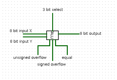
Your final ALU should look (approximately) like this when you use it as part of a larger circuit:
Logisim hint:If you have an 8-bit number and you want to access just the bits individually, you can use the Splitter located under Wiring. If you set "Fan Out" to 8 and "Bit Width In" to 8, you'll be able to turn any 8-bit input into 8 1-bit outputs. You can also do the reverse by simply connecting 8 1-bit inputs to one side of the splitter and getting 1 8-bit output back out.