CS31 Lab 3: Circuits
Part 2: Due before 11:59pm Tuesday, Sept 29
This lab should be done with a new assigned partner. You and your Lab 3 partner will work together for two weeks on both Part 1 and Part2 of lab 3.
Here is the Lab A partner list.
Here is the Lab B partner list.
- Part 1: consists of submitting your solution to part1.circ by the Part 1 due date.
- Part 2: consists of submitting your solution to alu.circ by the Part 2 due date.
Lab 3 Goals:
- To build and test digital cicuits.
- To understand how machine code instrutions are executed by digital circuits.
- To apply incremental implementation and testing to design.
Both you and your partner should do:
- Get your Lab03 ssh-URL from the GitHub server for our class: CS31-f15
- On the CS system, cd into your cs31/labs subdirectory
cd ~/cs31/labs
- Clone a local copy of your shared repo in your private
cs31/labs subdirectory:
git clone [your_Lab03_URL]
Then cd into your Lab03-you-partner subdirectory.
README.md alu.circ part1.circIf this didn't work, or for more detailed instructions see the the Using Git page.
As you and your partner work on your joint solution, you will want to push and pull changes from the master into your local repos frequently.
Logisim
You will use Logisim to create and test circuits. Take a look at some of the examples we did in lab for how to do different things in logisim. Also, see he Beginners Guide and Library Documentation of the Logisim web page for more help. To run:$ logisim # start a new session $ logisim alu.circ # run on an existing circuit file
- do the Beginner's Tutorial on the logisim web page (Logisim web page).
- try circuitizing the XOR circuit you built in the tutoial. Remove any clock and counter circuits from it. See Wednesday's lab page for directions.
- try adding a new circuit to the file (Project->Add Circuit), that implements a 4 bit version XOR we did on the board in class on Tuesday. Try changing the inputs to be 4 bits each instead of 1 bit each. In the main circuit add an instance of your 4-bit XOR circuit and test it out. (click on your XOR circuit from the menu and click on the canvas where you want ot place it)
- Before starting Part 2, try out some of the logisim circuits in a test.circ file and see if you can figure out what they do and how to configure them. The Logisim beginners guide and library reference are very helpful.
$ logisim part1.circEdit the text at the top of this file to list your and your partner's names.
Sign Extension
Sign extension is an common operation performed inside a CPU. It is used when combining a value(s) of types smaller than the registers holding the values. Create a circuit (Project→Add Circuit) that takes a 2-bit 2's complement number and performs sign extension so that the output is an equivalent 4-bit 2's complement number. Name this circuit something like signext2to4. Be sure to label each of your input and output values. Your input should be labeled so that the least significant input bit is a0 and the most significant input bit is a1. Following the same pattern, label your output bits b0 through b3.
1-bit Full Adder
Create a 1-bit full adder as a new circuit (Project→Add Circuit). Name this circuit fulladder. Your full adder should take 3 inputs (X, Y, CarryIn) and yield two outputs (Sum, CarryOut).
Start with the truth table for X + Y + C_in = Sum, C_out and then translate this into a circuit using basic gates only. (i.e. there is an adder circuit in logisim, you cannot use that to solve this problem, you have to build your own).
Once built, test out your cicuit for all possible input values.
4-bit Full Adder
Add a new circuit fulladder4 that takes 2 4-bit input values, x and y, and 1 1-bit input value, carry-in, and produces a 4-bit sum output value, and a 1-bit carry-out value. To build this circuit you should use four copies of your 1-bit adder to add each digit. The two 4-bit input values can be represented as a single input of size 4 and then you can use a splitter to get the value of each bit.
You do not need to worry about overflow, but you should add a probe to the carry out bit wire to see when it is 0 or 1.
Test out your 4-bit adder for differnt input values.
NOTE: The 4-bit adder you are building adds two 4-bit numbers, whether they are unsigned or 2's complement. The only difference has to do with overflow -- which you aren't dealing with in this question -- the addition is the same either way.Putting it all together
Finally, add a circuit named tester. In to this circuit add a copy of your 4-bit adder and a copy of your sign extender. You are going to build a test circuit with 3 input values:- one 4-bit value: x
- one 2-bit value: y
- one 1-bit value: carry_in
- one 4-bit value: the result of x + y
- one 1-bit value: carry_out
Test out your resulting cirucit for different input values. Use the poke tool to change the bits of an input value. Do NOT hook up a clock and a counter to this circuit's input; the 3 input values x, y, and carry_in should come from the input. You can use a counter for testing, but the version you submit should not have this.
In this part of the lab, you will implement part of an arithmetic logic unit. Your answer will be stored in alu.circ. The ALU is the part of the processor that performs mathematical and logical operations. Your ALU should use components from Logisim whenever possible. For example, do not build a 8-bit adder -- simply use the 8-bit adder that is already part of Logisim.
To use an 8-bit adder, open the Arithmetic folder and select Adder. The default Adder has "Data Bits" set to 8. That is an 8-bit adder. The inputs to an 8-bit adder are also 8-bits, so you need to hook up an 8-bit input pin. The output is 8-bits, so you need to hook up an 8-bit output pin. The carry-in and carry-out bits are only 1-bit each.
Requirements
Your ALU will perform 8 arithmetic functions on two 8-bit inputs, producing one 8-bit output, and five 1-bit ouputs (condition code flags). In addition it will have one 3-bit input, the opcode, which will select which of the 8 arithmetic functions to perform. Implement this in your circuit using a multiplexor with 8 inputs, one for each function result, and 3 select lines. (In Logisim, be sure to change "Include Enable?" from "Yes" to "No".) The function you perform will depend on the value of the 3 select lines. Assuming the inputs are called X and Y, you will perform:
- 000: X or Y
- 001: X and Y
- 010: X + Y
- 011: X - Y. Logisim contains a Subtractor circuit, however, I'd like you to not use it, and instead use an Adder circuit to perform subtraction as X + ~Y + 1. It is probably easier to not use the same Adder circuit for both the addition and subtraction operations (i.e. just have two Adder circuits in your solution, one for X+Y and the other for X-Y). You are welcome to try using a single Adder circuit for the two operations if you'd like. There is a constant that you can use for the c_in input to the Adder curcuit.
- 100: X <<Y. Shift left. e.g. 10111000 becomes
01110000. Note that Logisim has a Shifter gate that can be
customized to perform this and the next three
operations. Shifts X to the left Y times. Note: for the
three shift operations, the input Y to the Shifter can only
be 3 bits. Use a splitter to extract the last three bits of
Y, then use another splitter (in reverse) to build up a 3
bit wire from the 3 least significant digits. If
Y=01010100, you would shift
01010100 -- 4 places to the left. - 101: X >>Y (Shift right) without sign extension (also known as logical shift), e.g. 10111001 becomes 01011100, not 11011100. Shifts X to the right Y times; the input Y is still only 3 bits.
- 110: X >>Y (Shift right) with sign extension (also known as arithmetic shift), e.g. 10111001 becomes 11011100 and 01000001 becomes 00100000; the input Y is still only 3 bits.
- 111: X < Y? The output should be 00000001 if X < Y 00000000 otherwise. X and Y should be treated as 2's complement values. Logisim has a Comparator gate that can be customized to perform almost exactly what you need, but it only ouputs a 1-bit 0 or 1, so you'll need to figure out how to make that 8 bits.
- bit 0: EQ: the EQ flag is set to 1 when x and y are equal
- bit 1: OF: the OF flag is set to 1 when either x + y or x - y results
in SIGNED overflow. For all other operations, the OF flag should be set
to 0 (only ADD and SUB ops can result in overflow).
- bit 2: CF: the carry flag is set to 1 when either x + y or x - y
results in UNSIGNED overflow. For all other operations, the OF flag
should be set to 0 (only ADD and SUB ops can result in overflow).
- bit 3: ZF: the zero flag is set to 1 if the result is equal to zero
- bit 4: SF: the sign flag is set to 1 if the result is negative (as interpreted as an 8 bit 2's complement value)
In all other cases the flag bits should be zero.
Remember that the ALU does not know, nor does it care, if the operands are signed or unsigned values. It will set the OF and the CF flags to 0 or 1 on every addition or subtraction.
Circuit Layout
Your final ALU circuit should look like this when you use it as part of a larger circuit:
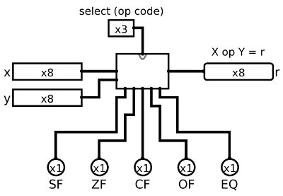
If your circuit layout does not match this, then right-click on your alu circuit in circuit menu and Choose Edit Circuit Appearance. Then move your input and ouput to the corresponding locations to match those above.
Implementation and Testing Hints
I suggest that you test your ALU curcuit as you go; add a little functionality, stop and test that functionality by trying out different input values using the poke tool, once that part works, then add a little more functionality ...
You may also want to add a tester circuit into which you can plop a copy of your alu, and from which you can do more extesive testing on your entire circuit. You could use counters and clocks here to cycle through a set of values if you'd like. You can also use input values stored in 3 ROMs: one for op; one for x; and one for y. Then use a counter and clock to feed addresses into the three ROMS to get the next set of x, y, and opcode input to test.
Logisim hint: If you have an 8-bit number and you want to access just the bits individually, you can use the Splitter located under Wiring. If you set "Fan Out" to 8 and "Bit Width In" to 8, you'll be able to turn any 8-bit input into 8 1-bit outputs. You can also do the reverse by simply connecting 8 1-bit inputs to one side of the splitter and getting 1 8-bit output back out.
The logic of the Flags will require some thought. I recommend working out one flag at a time, and working out the logic on paper first before trying to implement their circuitry. Think about what state a flag needs to determine if it needs to be set or cleared.
Before the Due Date
Only one of you or your partner needs to push your solution from one of your local repos to the GitHub remote repo. (it doesn't hurt if you both push, but the last pushed version before the due date is the one we will grade, so be careful that you are pushing the version you want to submit for grading):From one of your local repos (in your ~you/cs31/labs/Lab03-partner1-partner2 subdirectory)
git push
For both Part 1 and Part 2 you will be pushing files in the same Lab03 repo. Make sure for Part 1 you have committed and pushed part1.circ and for Part 2 you have committed and pushed alu.circ.
Troubleshooting
If git push fails, then there are likely local changes you haven't committed. Commit those first, then try pushing again:git add sorter.c git commit git pushAnother likely source of a failed push is that your partner pushed, and you have not pulled their changes. Do a git pull. Compile and test that your code still works. Then you can add, commit, and push.
If that doesn't work, take a look at the "Troubleshooting" section of the Using git page. You may need to pull and merge some changes from master into your local. If so, this indicates that your partner pushed changes that you have not yet merged into your local. Anytime you pull into your local, you need to check that the result is that your code still compiles and runs before submitting.