-
Checkpoint due 11:59pm Tuesday, February 12
-
Full Solution due 11:59pm Tuesday, February 19
1. Handy References
2. Lab 3 Goals:
-
Build, test, and simulate digital circuits.
-
Observe how machine code instructions are executed by digital circuits.
-
Apply incremental implementation and testing to design.
3. Lab Description
For this lab, you will use logic simulation software (Logisim) to construct your very own arithmetic logic unit (ALU). This lab is longer than the previous two, so you’ll be given two weeks to complete it, with a checkpoint submission at the half-way point.
To get started, clone your Lab 3 git repository from Swarthmore’s GitHub.
-
You should see two
.circfiles (part1.circandalu.circ). Use these files for your solution to Part 1 (checkpoint) and Part 2 (full solution).
4. Part 1 (Checkpoint): Sign extender and adder.
All the circuits for this part should be in a single file named part1.circ.
|
Use Simple Gates Only for Part 1 Checkpoint
There are built-in Logisim circuits that do sign-extension and addition. You should not use those for this part: you are building these circuits from simple gates (AND, OR, NOT, and XOR only), inputs, outputs and splitters. You are, however, welcome to test the behavior of your circuits against the built-in versions to convince yourself of correctness. |
$ logisim part1.circ
Edit the text at the top of this file to list your names.
4.1. Sign Extension
Sign extension is an common operation performed inside a CPU. It is used when combining a value(s) of types smaller than the registers holding the values.
-
Create a circuit (Project→Add Circuit) that takes a 2-bit
2’scomplement number and performs sign extension so that the output is an equivalent 4-bit 2’s complement number. -
Name this circuit something like signext2to4. Be sure to label each of your input and output values.
4.2. 1-bit Full Adder
Create a 1-bit full adder as a new circuit (Project→Add Circuit). Name this circuit fulladder.
-
Your full adder should take 3 inputs (
X,Y,CarryIn) and yield two outputs (Sum,CarryOut). -
Start with the truth table for X + Y + C_in = Sum, C_out and then translate this into a circuit using basic gates only (i.e., there is an adder circuit in Logisim, you cannot use that to solve this problem, you have to build your own).
Once built, be sure to test out your circuit for all possible input values to ensure that it’s implemented correctly!
4.3. 4-bit Full Adder
Add a new circuit fulladder4 that takes two 4-bit input values, x and y, and one 1-bit input value, carry-in, and produces a 4-bit sum output value, and a 1-bit carry-out value.
-
To build this circuit you should use four copies of your
1-bitadder to add each digit. -
The two 4-bit input values can be represented as a single input of size 4 and then you can use a
splitterto get the value of each bit.
| The 4-bit adder you are building adds two 4-bit numbers, whether they are unsigned or 2’s complement. The only difference has to do with overflow — which you aren’t dealing with in this question — the addition is the same either way. |
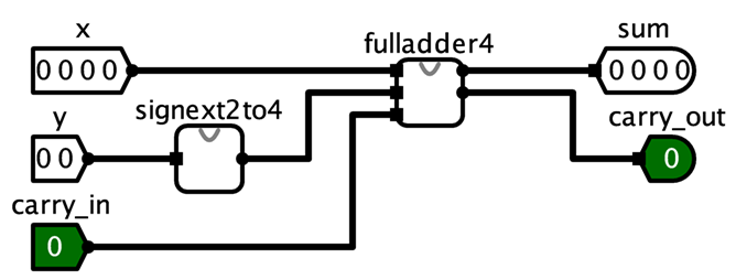
4.4. Putting it all together
Finally, in part1.circ’s main circuit, add a copy of your 4-bit adder and a copy of your sign extender. You are going to build a test circuit with three input values:
-
one 4-bit value:
x -
one 2-bit value:
y -
one 1-bit value:
carry_in
and two output values:
-
one 4-bit value: the result of
x + y -
one 1-bit value:
carry_out
The input value y, will need to be sign-extended before it is added to x.
Test out your resulting circuit for different input values. Use the poke tool to change the bits of an input value.
4.5. Circuit Layout
This will make grading much easier. Please make the grader happy, everyone benefits from a happy grader!
Your final ALU circuit should look like this when you use it as part of a larger circuit:
5. Part 2 (Full Solution): Building an ALU.
In this part of the lab, you will implement part of an arithmetic logic unit. Your answer will be stored in alu.circ.
The ALU is the part of the processor that performs mathematical and logical operations. Unlike part-1 above, your ALU should use built-in components from Logisim whenever possible (with the exception of the subtractor, see the requirements below).
For example, you do not need to build an 8-bit adder — you may simply use the 8-bit adder that is part of Logisim. You know how to build an adder already, so let’s take advantage of some abstraction!
8-bit adder:
-
To use an
8-bit adder, open theArithmeticfolder and selectAdder. The defaultAdderhas "Data Bits" set to 8. That is an8-bit adder. -
The inputs to an
8-bit adderare also8-bits, so you need to hook up an8-bit input pin. The output is 8-bits, so you need to hook up an8-bit output pin. -
The carry-in and carry-out bits are only
1-biteach.
6. Requirements
-
Your ALU will perform eight arithmetic functions on two
8-bitinputs, producing one8-bitoutput, and five1-bitoutputs (condition code flags). -
It will have one
3-bit input, the opcode, which will select which of the eight arithmetic functions to perform. -
Implement this in your circuit using a
multiplexorwith eight inputs, one for each function result, and three select lines. (In Logisim, be sure to change "Include Enable?" from "Yes" to "No").
The function you perform will depend on the value of the three select lines. Assuming the inputs are called X and Y, you will perform:
-
000: X or Y -
001: X and Y -
010: X + Y -
011: X - Y -
100: X <<YShift left, e.g.10111000becomes01110000.Note that Logisim has a Shiftergate that can be customized to perform this and the next three operations. Shifts X to the left Y times. For the three shift operations, the input Y to theShiftercan only be three bits. Use asplitterto extract the last three bits of Y, then use anothersplitter(in reverse) to build up a3-bitwire from the three least significant digits. IfY=01010100, you would shift01010100— 4 places to the left. -
101: X >>Y(Shift right) without sign extension (also known as logical shift), e.g.10111001becomes01011100, not11011100. Shifts X to the right Y times; the input Y is still only 3 bits. -
110: X >>Y(Shift right) with sign extension (also known as arithmetic shift), e.g.10111001becomes11011100and01000001becomes00100000; the input Y is still only 3 bits. -
111: X < Y?The output should be00000001if X < Y,00000000otherwise. X and Y should be treated as 2’s complement values. Logisim has acomparatorgate that can be customized to perform almost exactly what you need, but it only outputs a1-bit0or1, so you’ll need to figure out how to make that eight bits.
|
Logisim’s Subtractor and Negator Circuit
Logisim contains a Subtractor and a Negator circuit, however, we would like you to not use it, and instead use an Adder circuit to perform subtraction as X + ~Y + 1. It is probably easier to not use the same Adder circuit for both the addition and subtraction operations (i.e. just have two Adder circuits in your solution, one for X+Y and the other for X-Y). You are welcome to try using a single Adder circuit for the two operations if you’d like. There is a constant that you can use for the c_in input to the Adder circuit. |
6.1. Output Flags
Your ALU should also have five 1-bit output flags. An output flag’s value should be zero, unless it is specifically set as a side-effect of a arithmetic operation; think of it as clearing the flag bits "between" each arithmetic operation.
Your processor will output the following flag bits:
-
bit 0:EQ: The EQ flag is set to 1 when x and y are equal. -
bit 1:OF: For addition and subtraction, the OF flag is set to 1 when the requested operation results in SIGNED overflow. In other words:-
if the opcode says to add (
010), this flag should only be set to 1 if the addition represents signed overflow, and -
if the opcode says to subtract (
011), this flag should only be set to 1 if the subtraction represents signed overflow. -
You may want to review the course slides for a discussion of what does/doesn’t constitute overflow. For all other operations, you can set this flag to zero.
-
-
bit 2:CF: For addition and subtraction, the carry flag is set to 1 when the requested operation results in UNSIGNED overflow. Its behavior is similar to that of theOF flag(above), only here we’re considering UNSIGNED overflow. For all other operations, you can set this flag to zero. -
bit 3:ZF: The zero flag is set to 1 if the result is equal to zero -
bit 4:SF: The sign flag is set to 1 if the result is negative (when interpreted as an 8 bit 2’s complement value)
In all other cases the flag bits should be zero.
Remember that the ALU does not know, nor does it care, if the operands are signed or unsigned values. It will set the OF and the CF flags to 0 or 1 on every addition or subtraction.
6.2. Circuit Layout
This will make grading much easier. Please make the grader happy, everyone benefits from a happy grader!
Your final ALU circuit should look like this when you use it as part of a larger circuit:
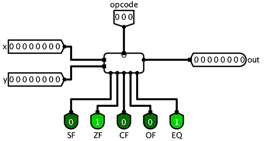
If your circuit layout does not match this, then right-click on your ALU circuit in circuit menu and Choose Edit Circuit Appearance. Then move your input and output to the corresponding locations to match those above.
7. Tips
-
I suggest that you test your ALU circuit often as you go; add a little functionality, stop and test that functionality by trying out different input values using the poke tool, once that part works, then add a little more functionality …
-
If you have an 8-bit number and you want to access just the bits individually, you can use the
Splitterlocated under Wiring. If you set "Fan Out" to 8 and "Bit Width In" to 8, you’ll be able to turn any 8-bit input into 8 1-bit outputs. You can also do the reverse by simply connecting 8 1-bit inputs to one side of the splitter and getting 1 8-bit output back out. -
Occasionally Logisim will, for lack of a better description, "freak out" on you for no apparent reason and decide that none of your components are connected to each other, even when they clearly are. If you all of a sudden see tons of wires turn blue or red and connections stop making sense, save your work, exit Logisim, and reopen your saved file.
8. Submitting
To submit your circuit files, simply commit your changes locally using git add and git commit. Then run git push while in your lab directory. Only one partner needs to run the final push, but make sure both partners have pulled and merged each others changes. See the section on Using a shared repo on the git help page.
Note: When I clone your repositories, I will grab both the part1.circ and alu.circ when you submit for both your checkpoint and full solution. Don’t worry about that. We will only look at your part1.circ for the checkpoint, and we will only look at alu.circ for the full solution even though part1.circ will be submitted again.