-
Checkpoint (Part 1): Due by 11:59 pm, Thursday, September 28, 2023
-
Completed lab (Parts 1 and 2): Due by 11:59 pm, Thursday, October 5, 2023
You will work with your assigned partner on this Lab 3 Partners
1. Lab 3 Goals:
-
Build, test, and simulate digital circuits.
-
Observe how machine code instructions are executed by digital circuits.
-
Apply incremental implementation and testing to design.
2. Lab Overview
For this lab, you will use logic simulation software (Logisim) to construct your very own arithmetic logic unit (ALU). This lab is longer than the previous two, so you’ll be given two weeks to complete it, with a checkpoint submission between the two parts.
3. Lab Starting Point Code
3.1. Getting Your Lab Repo
Both you and your partner should clone your Lab repo into
your cs31/labs subdirectory:
-
Get your lab repo’s SSH URL from the CS31 git org. The repository to clone is named
Lab03-user1-user2, where user1 and user2 are the user names of you and your Lab partner. -
cdinto yourcs31/labssubdirectory:$ cd ~/cs31/labs $ pwd -
clone your repo
$ git clone [your_Lab03_repo_url]
There are more detailed instructions about getting your lab repo from the "Getting Lab Starting Point Code" section of the Using Git for CS31 Labs page.
3.2. Starting Point Code
-
part1.circis the file you should use for your solution to Part 1 (checkpoint). -
alu.circis the file you should use for your solution to Part 2 (full solution).
4. Part 0: Getting Started in Logisim
You do not need to submit anything for this part, but you should trying some things out in logisim before jumping into the two required parts of the lab.
Start by going through the Logisim Beginner’s Tutorial and
try out building the XOR circuit. Run logisim with no arguments to
start a new circuit. Use the & to run logisim in the background:
$ logisim &Choose "File→Save As" to choose a file name (and location) for the tutorial circuit. Then follow along the tutorial to build an XOR circuit and test it.
You can also try changing the inputs and outputs to be 4 bits each instead of 1 bit each. And you could try creating a new circuit for this (Project→Add Circuit) and adding some circuitry for testing the circuit, like we did for the in-lab assignment.
Before starting Part 2, you may want try out some of the logisim
circuits (you can just do this in your test.circ file).
See if you can figure out what some of the circuits do and how to
configure them. Refer to some of the logisim beginners guide and other logisim references listed in the Handy Resources at the end of the webpage.
5. Part 1: Sign extender and adder.
All the circuits for this part should be in a single file named part1.circ:
$ logisim part1.circ &|
You may only use Simple Gates in your solution to Part1. There are built-in Logisim circuits that do sign-extension and addition. You should not use those for this part: you are building these circuits from simple gates (AND, OR, NOT, and XOR only), inputs, outputs and splitters. You are, however, welcome to test the behavior of your circuits against the built-in versions to convince yourself of correctness. |
You should add your test cases to the file named part1_testing.txt.
5.1. Sign Extension
Sign extension is an common operation performed inside a CPU. It is used when combining a value(s) of types smaller than the registers holding the values.
-
Create a new circuit (Project→Add Circuit) named signext2to4 that takes a 2-bit two’s-complement number and performs sign extension so that the output is an equivalent 4-bit 2’s complement number.
-
Your sign extender should take one two-bit input (
in) and produce one four-bit output (out) with the sign-extended 4-digit binary number. Be sure to label these in the circuit.
5.2. 1-bit Full Adder
-
Create a new circuit (Project→Add Circuit) named fulladder that implements a 1-bit full adder.
-
Your full adder should take 3 inputs (
X,Y,CarryIn) and yield two outputs (Sum,CarryOut). -
Start with the truth table for
X + Y + CarryIn = Sum, CarryOutand then translate this into a circuit using basic gates only (i.e., there is an adder circuit in Logisim, you cannot use that to solve this problem, you have to build your own). -
It will be helpful for the next part of the lab if you have the
XandYpins facing East, theCarryInpin facing South, theSumpin facing West, and theCarryOutpin facing North.
Once built, be sure to test out your circuit for all possible input values to ensure that it’s implemented correctly!
5.3. 4-bit Full Adder
-
Create a new circuit (Project→Add Circuit) named fulladder4 that implements a 4-bit full adder.
-
The circuit takes two 4-bit input values,
XandY, and one 1-bit input value,CarryIn, and produces a 4-bitSumand a 1-bitCarryOut. -
To help with grading, have your input values all facing East with
X,YandCarryIngoing from top to bottom and have your output values all facing West withSumaboveCarryOut. See Section 5.5 for more information. -
To build this circuit you should use four copies of your 1-bit fulladder circuit to add each digit.
-
The two 4-bit input values should be represented as a single 4-bit input. You can then use a Splitter to extract the value of each bit.
|
The 4-bit adder you are building adds two 4-bit numbers, whether they are unsigned or 2’s complement. The only difference has to do with overflow — which you aren’t dealing with in this question — the addition is the same either way. |
5.4. Putting it all together
Finally, in part1.circ’s main circuit, add a copy of your 4-bit adder and a
copy of your sign extender. You are going to build a test circuit with three
input values:
-
one 4-bit value:
X -
one 2-bit value:
Y -
one 1-bit value:
CarryIn
and two output values:
-
one 4-bit value:
Sum, the result ofX + Y -
one 1-bit value:
CarryOut, the carry out fromX + Y
The input value Y, will need to be sign-extended before it is added to X.
Test out your resulting circuit for different input values. Use the "Poke" tool to change the bits of your input values.
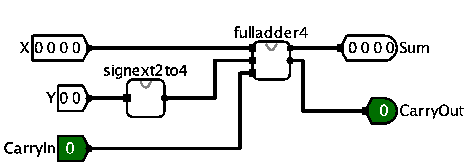
5.5. Circuit Layout
This will make grading much easier. Please make the grader happy, everyone benefits from a happy grader!
Your final circuit should look like this when you use it as part of a larger circuit:
5.6. Testing your circuits
Before submitting your final version of part1.circ, you should thoroughly
test your circuits with a variety of inputs and verify that the outputs match
what you expect. Your repo contains a file named part1_testing.txt that asks
you to:
-
run two test cases through your circuit and record your results
-
predict the results of two test cases before checking the results in your circuit
-
develop two new test cases and checking the result in your circuit
Note that the test cases listed in part1_testing.txt are NOT exhaustive — you should still test other cases too, until you’re fully convinced that the
circuit it behaving correctly.
6. Part 2: Building an ALU
In this part of the lab, you will implement part of an arithmetic logic unit.
Your answer will be stored in alu.circ. The ALU is the part of the processor
that performs mathematical and logical operations.
|
Unlike part 1 above, your ALU should use built-in components from Logisim whenever possible (with the exception of the subtracter, see the requirements below). For example, you do not need to build an 8-bit adder — you may simply use the "Adder" that is part of Logisim and set its Data Bits to 8. You know how to build an adder already, so let’s take advantage of some abstraction! More specifically, if you wanted to have an 8-bit adder in your circuit, you would perform the following steps:
|
6.1. Requirements
-
Your ALU will perform eight arithmetic functions on two 8-bit inputs, producing one 8-bit output, and five 1-bit outputs (condition code flags).
-
It will have one 3-bit input, the opcode, which will select which of the eight arithmetic functions to perform.
-
The ALU will select which of the eight arithmetic outputs to use by using a Plexers→Multiplexer with eight data inputs, one for each arithmetic result, and one 3-bit select input (the opcode). Be sure to change "Include Enable?" from "Yes" to "No". The arithmetic function that the ALU selects depends on the value of opcode. Assuming the inputs are called X and Y, the ALU operation selected for by the opcode is:
-
000:X or Y. Performs bit-wise or. Use Logisim’s built-in Or gate. -
001:X and Y. Performs bit-wise and. Use Logisim’s built-in And gate. -
010:X + Y. -
011:X - Y. You must implement subtraction asX + ~Y + 1. Do not use the Logisim Arithmetic→Subtractor. -
100: Shift Left. ShiftsXleft byYpositions. See the note below on this and the next three operations. -
101: Logical Shift Right. ShiftsXright byYpositions without sign extension. -
110: Arithmetic Shift Right. ShiftsXright byYpositions with sign extension. -
111:X < Y?. The output should be00000001ifX < Y;00000000otherwise.XandYshould be treated as two’s complement values. Logisim has an "Arithmetic→Comparator" gate that can be customized to perform almost exactly what you need, but it only outputs a 1-bit0or1, so you’ll need to figure out how to make that eight bits.
-
-
Note on the three Shift operations. Logisim has an Arithmetic→Shifter that can be customized to perform all three Shift operations. For each operation, the Shifter expects the second input,
Y, to be only 3 bits, but your inputYis 8 bits. Use a Splitter to extract the last three bits ofY, then use another Splitter in reverse to build up a 3-bit wire from the three least significant digits. For example, if your inputYis01010100, you would keep only the last 3 digits,100, as the second input to the Shifter.
|
Do Not Use Logisim’s Subtractor and Negator Circuits
Logisim contains a Subtractor and a Negator circuit, however, you are not
allowed to use these in your ALU. Instead use an Adder circuit to
perform subtraction as |
|
It is easier to use two different Adder circuits when implementing the addition and subtraction operations (i.e. one for |
6.2. Output Flags (Condition Codes)
Your ALU should also have five 1-bit output flags. Each output flag’s value should be zero unless it is specifically set as a side-effect of the selected arithmetic operation; think of it as clearing the flag bits "between" each arithmetic operation.
Your ALU will output the following flag bits:
-
bit 0:EQ: The EQ flag is set to 1 when x and y are equal. -
bit 1:OF: For addition and subtraction, the OF flag is set to 1 when the requested operation results in SIGNED overflow. In other words:-
If the opcode says to add (
010), this flag should only be set to 1 if the addition represents signed overflow, and -
If the opcode says to subtract (
011), this flag should only be set to 1 if the subtraction represents signed overflow. -
For all other operations, you should set this flag to zero.
you may want to review the course slides for a discussion of what does/doesn’t constitute overflow.
-
-
bit 2:CF: For addition and subtraction, the carry flag is set to 1 when the requested operation results in UNSIGNED overflow. Its behavior is similar to that of theOF flag(above), only here we’re considering UNSIGNED overflow. For all other operations, you should set this flag to zero. -
bit 3:ZF: The zero flag is set to 1 if the result is equal to zero -
bit 4:SF: The sign flag is set to 1 if the result is negative (when interpreted as an 8 bit 2’s complement value)
In all other cases the flag bits should be zero.
Remember that the ALU does not know, nor does it care, if the operands are
signed or unsigned values. It will set the OF and the CF flags to 0 or 1
on every addition or subtraction.
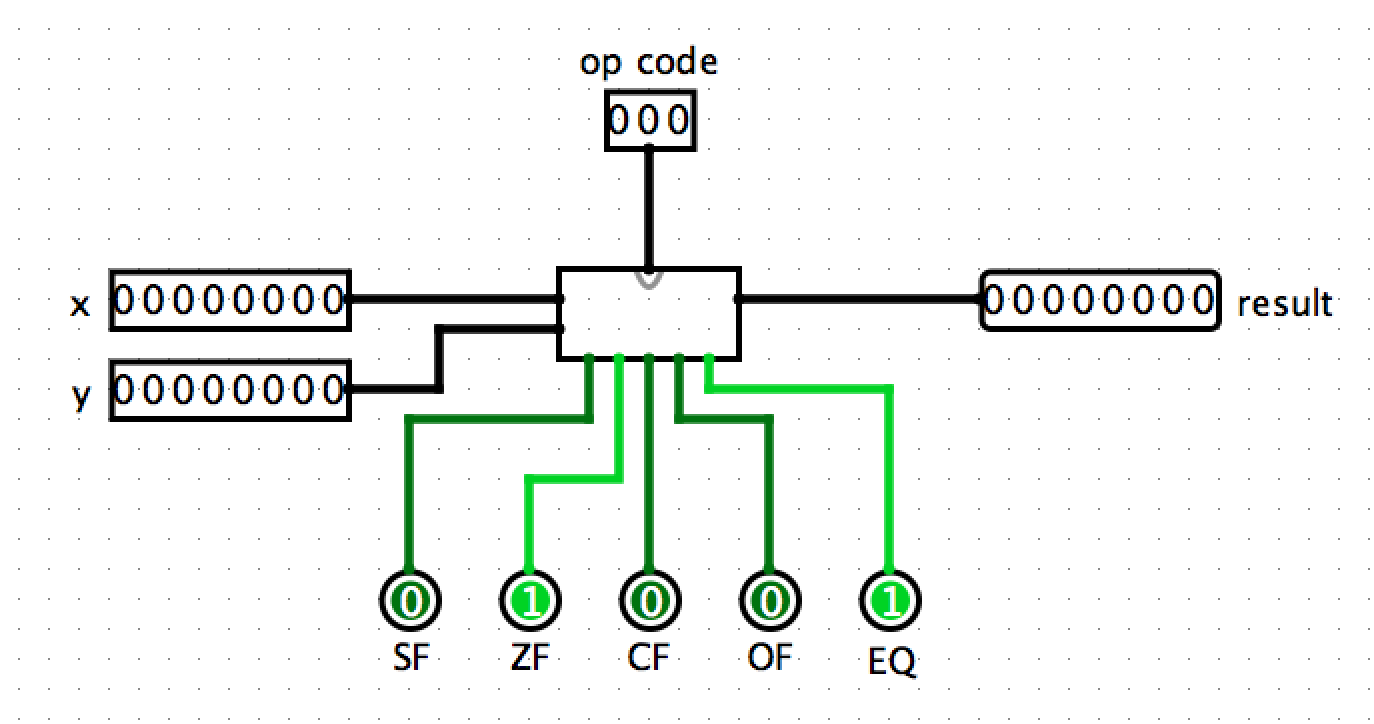
6.3. Circuit Layout
This will make grading much easier. Please make the grader happy, everyone benefits from a happy grader!
Your final ALU circuit (the box in the middle) must look like this (including the positions of all inputs and outputs) when you use it as part of a larger circuit:
If your circuit layout does not match this, then right-click on your ALU
circuit in circuit menu and Choose Edit Circuit Appearance. Then move your
inputs and outputs to the corresponding locations to match those above.
7. Survey
Once you have submitted the final version of your entire lab, you should submit the required Lab 3 Questionnaire (each lab partner must do this). Note that the survey should be turned in after your lab is turned in, therefore the deadline for the survey is deliberately left vague. You should submit it, but if it’s a bit later than the deadline for the actual lab (even by a day or two), that’s completely fine.
8. Tips
-
I suggest that you test your ALU circuit often as you go; add a little functionality, stop and test that functionality by trying out different input values using the poke tool, once that part works, then add a little more functionality …
-
You may also want to add a tester circuit into which you can plop a copy of your alu, and from which you can do more extensive testing on your entire circuit. You could use counters and clocks here to cycle through a set of values if you’d like. You can also use input values stored in 3 ROMs: one for op; one for x; and one for y. Then use a counter and clock to feed addresses into the three ROMS to get the next set of x, y, and opcode input to test. If you do this make sure the tester circuitry is in a separate subcircuit from your main ALU circuit
-
If you have an 8-bit number and you want to access just the bits individually, you can use the
Splitterlocated under Wiring. If you set "Fan Out" to 8 and "Bit Width In" to 8, you’ll be able to turn any 8-bit input into 8 1-bit outputs. You can also do the reverse by simply connecting 8 1-bit inputs to one side of the splitter and getting 1 8-bit output back out. -
Occasionally Logisim will, for lack of a better description, "freak out" on you for no apparent reason and decide that none of your components are connected to each other, even when they clearly are. If you all of a sudden see tons of wires turn blue or red and connections stop making sense, save your work, exit Logisim, and reopen your saved file. Also, save changes frequently as you go.
-
The logic of the flags (condition codes) will require some thought. I recommend implementing one flag at a time, and working out the logic on paper with a truth table before trying to implement the circuitry. Make sure you test the behavior of the flags in a variety of different situations.
The OF and CF flags will require the most thought and testing to get right. I suggest starting with SF, ZF, and EQ first, and testing them before trying OF and CF.
Step through some examples of operations applied to different values, and consider what the flag values should be. For instance:
-
If the opcode is 011 (subtraction), x is 00000000 and y is 00000001 then the result should be 11111111 and the flags should be set as follows: SF: 1, ZF: 0, CF: 1, OF: 0, EQ: 0 (subtracting 1 from zero results in unsigned overflow (CF) but not signed overflow (OF)).
-
If the opcode is 010 (addition) and x and y are both 01000001 then the result should be 10000010 and the flags should be set as follows: SF: 1, ZF: 0, CF: 0, OF: 1, EQ: 1.
There are also cases where both OF and CF should be set as well as cases where neither should be set. Test out your circuit for as many different kinds of inputs as you can think of.
-
9. Submitting
To submit your circuit files, simply commit your changes locally using git
add and git commit. Then run git push while in your lab directory. Only
one partner needs to run the final push, but make sure both partners have
pulled and merged each others changes.
For example, here are the commands to submit your part 1 solution
(use similar commands to submit alu.circ for part2):
$ git commit -am "part1 completed"
$ git push

-OR-

$ git add part1.circ
$ git commit -m "part1 completed"
$ git push
Note: When I clone your repositories, I will grab both the part1.circ and
alu.circ when you submit for both your checkpoint and full solution. Don’t
worry about that. We will only look at your part1.circ for the checkpoint,
and we will only look at alu.circ for the full solution even though
part1.circ will be submitted again.
If you have difficulty pushing your changes, see the "Troubleshooting" section and "can’t push" sections at the end of the Using Git for CS31 Labs page. And for more information and help with using git, see the git help page.
10. Handy Resources
-
Class EdSTEM page for questions and answers about lab assignment